IS300 with G35 accelerator pedal installation and Drive-By-Wire configuration
**page under construction**..but it's functional for now, I'm updating it when I have time, I have a mechanic background NOT a web design background.
|
YouTube Video here
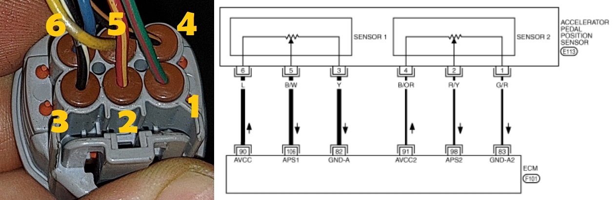
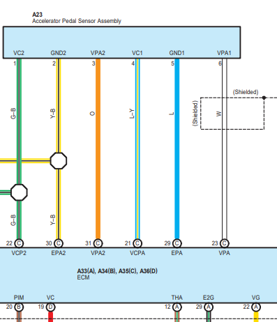
G35/350z Accelerator Pedal Pinout(multipled Nissan/Infinity's use this sensor, pins are the same, wire colors are different).
>br>Wiring described at #:## of this a href video
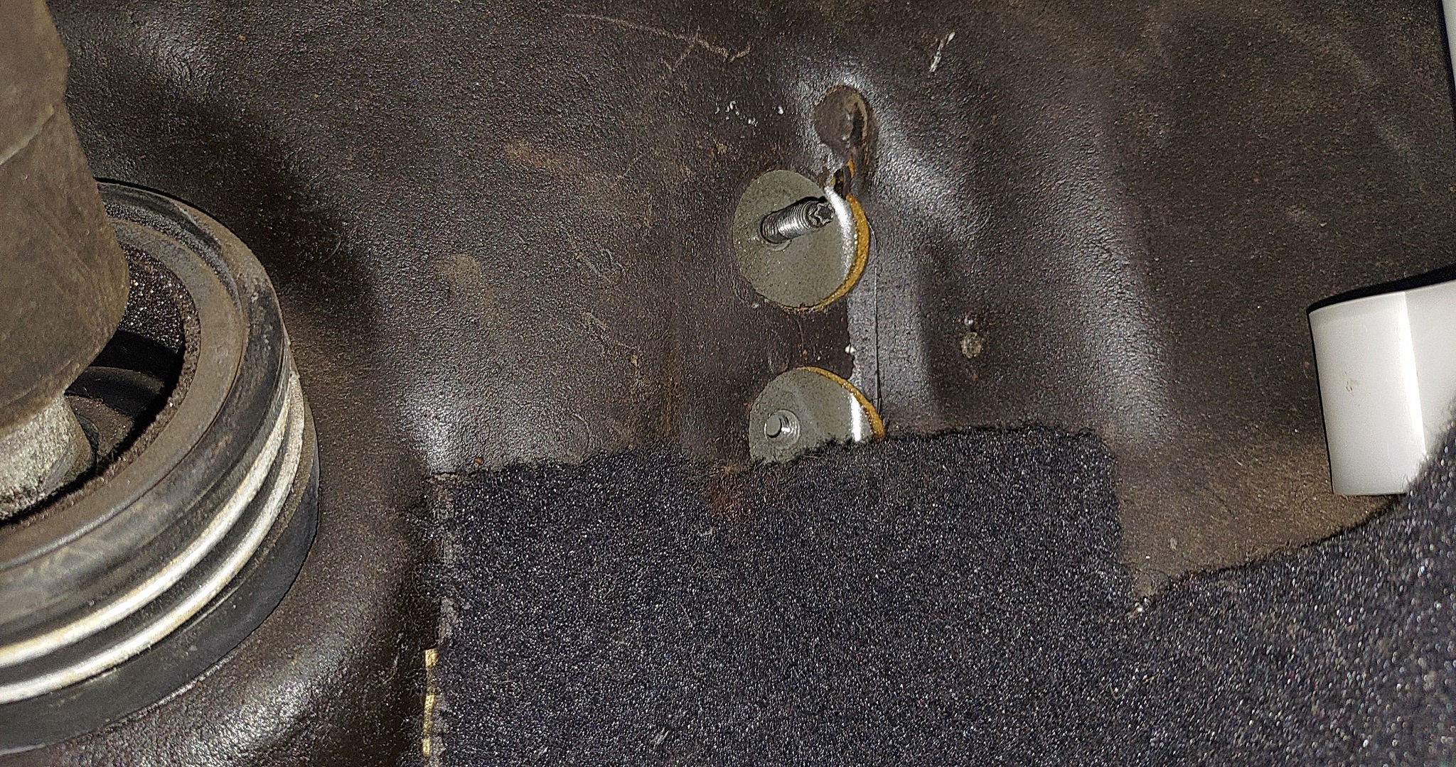
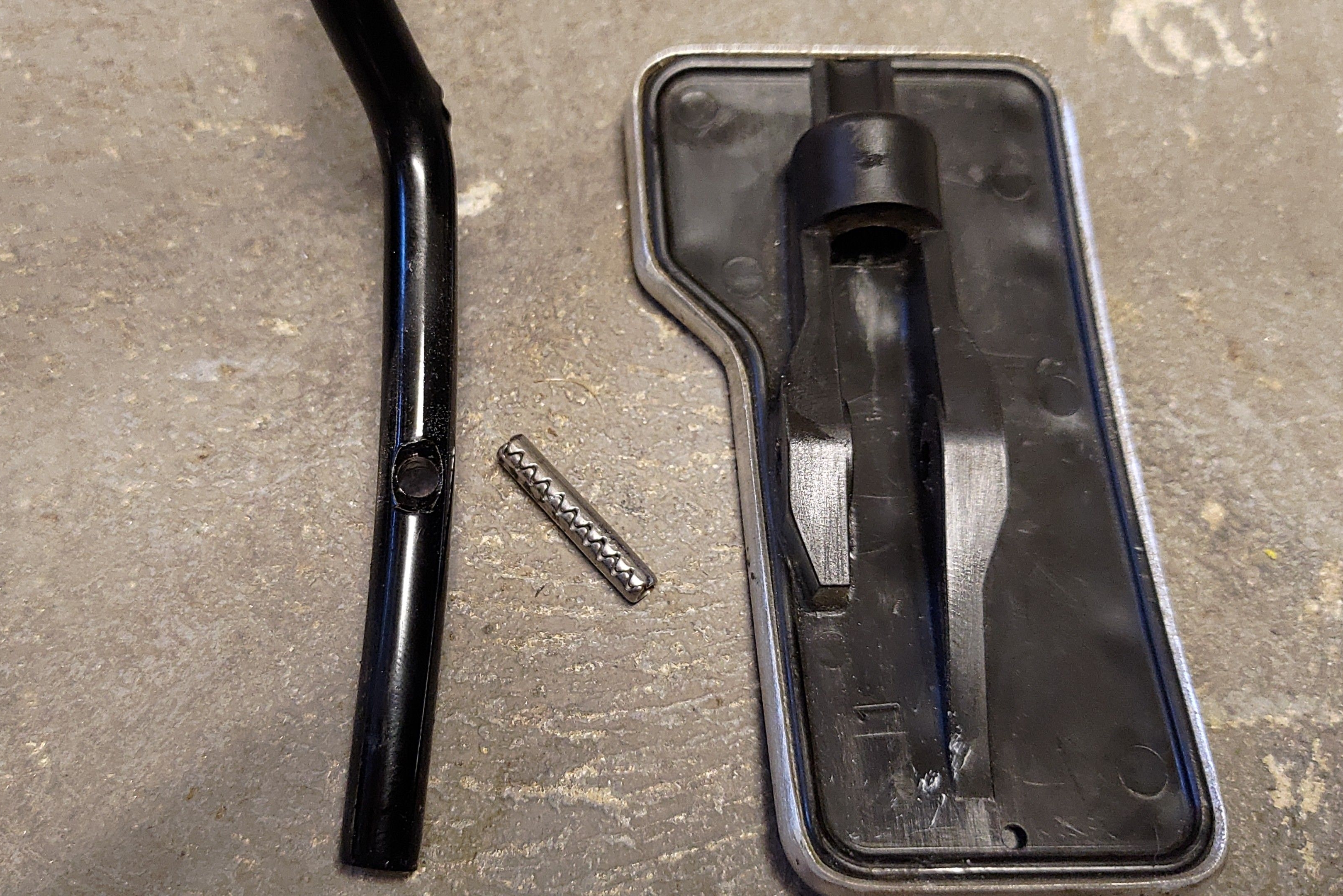
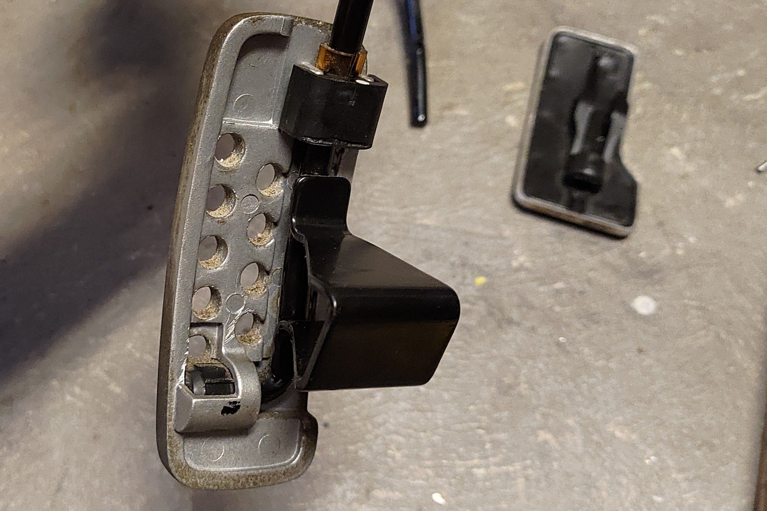
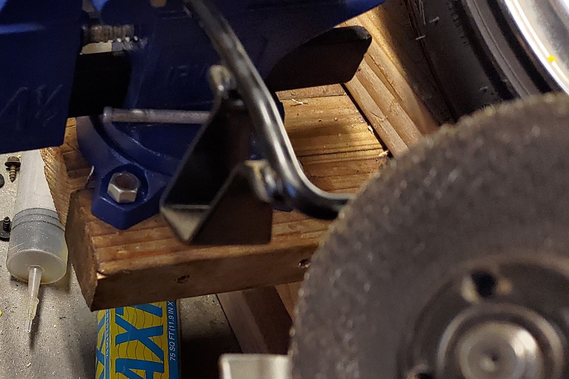
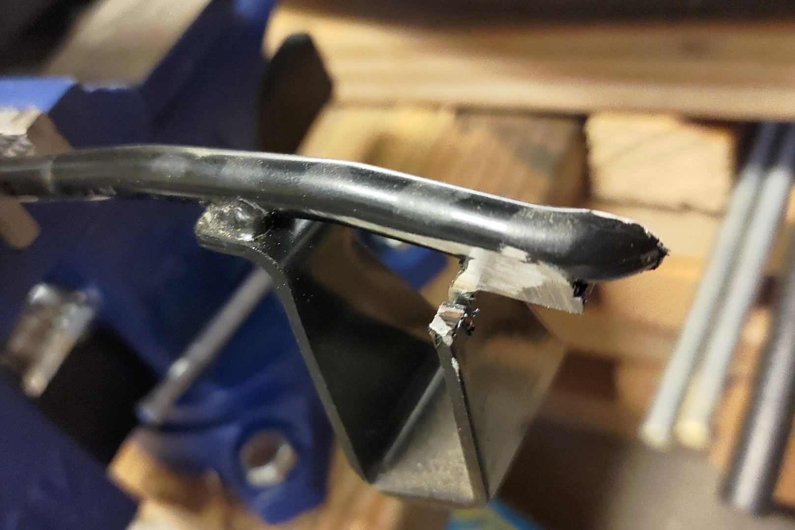
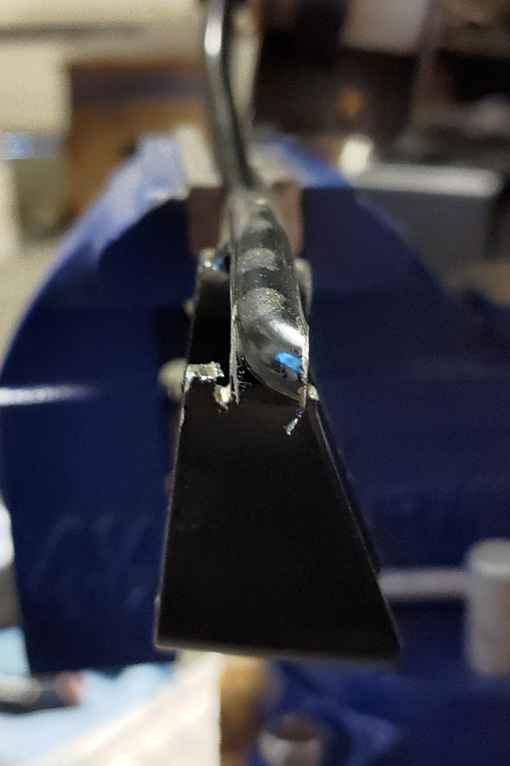
pins 1 and 3 are sensor ground. -(NOT chassis ground), connect to the ECU. pins 4 and 6 are 5v in. -connect 5v from your ECU. pin 2 is sub pedal sensor signal 2 (APS2). pin 5 is main pedal sensor signal 1 (APS1). connect pins 2 and 5 to your ECU input. note 1: "ECU" mentioned above refers to your engine management. note 2: this setup is preferred as it has a cheap replacement sensor that's easily sourced ($20 for OEM). Advantages/Disadvantages described at #:## and #:## of a href this video Advantages: Direct bolt in to firewall and cheap sensor that's easy to source and replace. Disadvantages: Requires bending pedal arm forward 30 degrees and CANNOT be used with OEM IS300 ECU. Fitment instructions Step 1: Bend pedal arm forward 30 degrees. Step 2: Source two 1.5 inch m6x1.0 bolts. Optional extra steps Step 3: Install a 2 inch long m6x1.00 stud on the top pedal mount hole on the firewall (makes installation easier). Step 3.5: Ignore steps 4-8 if you can weld. cut both pedal arms, weld the IS300 lower on the G35 upper. Done! Step 4: Remove your IS300 pedal pad with a punch tool. Step 5: Grind off the G35 pedal 90 degree tip Step 6: Grind off excess around the pedal arm bottom end to allow it to fit into the IS300 pedal pad. Step 7: Fasten the IS300 pad on the G35 pedal arm with old coat hanger or thick copper wire in a "U" shape Step 8: Use epoxy to hold everything steady, the wire holds it on the pedal arm, epoxy just ensures it stays still |
||||||
|
FR-S/BRZ APPS pinout
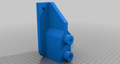
Pinout from HPAcademy: Pins 1 and 4 are 5V from your ECU Pins 2 and 5 are Sensor ground Pin 3 DBW - APP2 Pin 6 DBW - APP1 note 1: "ECU" mentioned above refers to your engine management. note 2: potentially the same pinout as the IS250/IS350 from 06->, needs verification. note 3: APPS1 and APPS2 can go to either APPS 1 or 2 inputs on the Haltech ECU. It will determine which is which during calibration. Advantages: The foot pad matches the IS300 brake/clutch style. No other advantages come to mind except how easily the parts are to find used on eBay. Disadvantage 1: Custom mount needed in order to adapt to your firewall Disadvantage 2: Sensor/Pedal assembly are one whole unit. Expensive to replace if it fails. STL (3D print) file on the left. This is something I found on STLfinder.com. It's for the IS250 06/07, but the bracket looks similar to the BRZ/FR-S mount points, so it may work or need some slight modification to fit a BRZ/FR-S pedal. |
|||||||
|
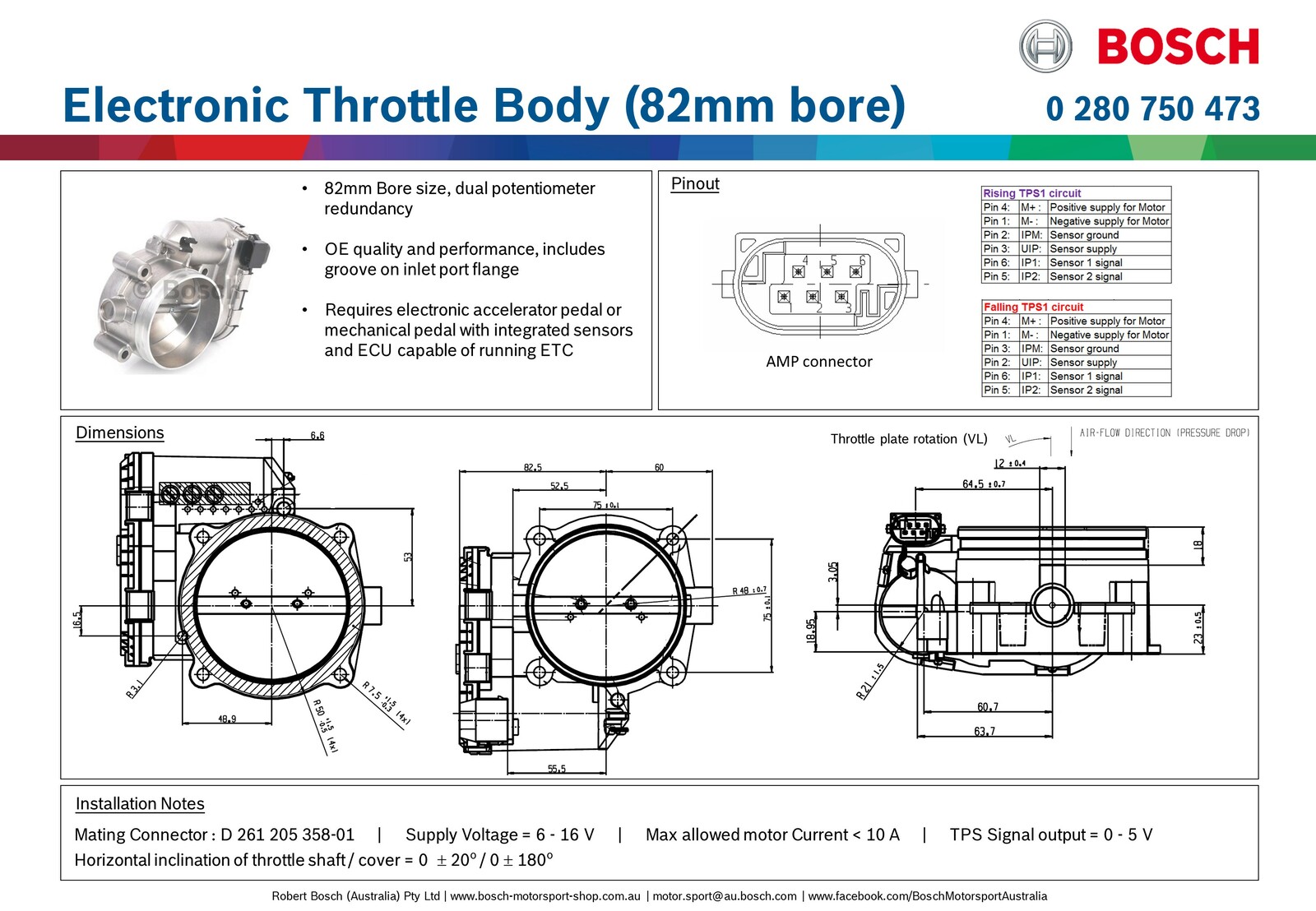
Bosch DBW pinout
Applies to most Bosch DBW (except 52mm). Verify with part number listing (link below) for other Bosch DBW TBs Pin 4: Motor+ Pin 1: Motor- Pin 2: Sensor Ground Pin 3: 5v Supply Pin 6: TPS 1 signal Pin 5: TPS 2 signal Note 1: Data sheet calls for 6v-16v supply signal, this is referring to the voltage to the DBW motor and not the sensor supply voltage. Verifiable via Haltech's 82mm Bosch info sheet. Note 2: Using this throttle body requires an adapter (see website below) Note 3: TPS 1 and TPS 2 on the DBW can go to either TPS 1 or TPS 2 respectively on the Haltech ECU, the Haltech determines which is which during calibration. Advantages: Bosch reliability, plus all of the drive-by-wire advantages, and it's easy to source a replacement if needed. Disadvantages: Engine management is required and adapters can be pricey unless you can source a cheap one or know a welder who will weld the flange on your manifold. OutsiderGarage.com: Website with multiple throttle body flanges, adapters, and wire pigtails. Click here for the Bosch part number listing for each DBW size with pinout comparisons! |