2JZ
**page under construction** Hover over image to animate, or click to bring up the document.
|
Click here to download the spreadsheet. The spreadsheet is fully editable and can be edited via Excel or LibreOffice Calc. Jump to video on YouTube here. |
1) Measure shims (or shimless buckets) thickness, input in column "E". 2) Install camshaft and torque your cam cap bolts to spec. 3) Measure actual clearance with feeler gauge between all shims and the back of the lobe (see note 1) and input measurements in column "C". 4) Input desired clearance from your cam card or service manual into column "D". 5) See shim size in column "K" and the associated part number in column "L". Want it more precise? Follow these extra steps! 6) Highlight cells F7-F18, copy, then highlight G7-G18 and right-click then Paste Special-Values (important, see note 2). 7) Remove camshaft, swap shim sizes that are close in size, then note them on the spreadsheet in column "E". 8) Reinstall camshaft, retorque cam caps, remeasure clearance with feeler gauge, and input NEW values in column "C" 9) COMPARE columns "F" to "G". Column "G" contains the first set of measurements (steps 1-4), and column "F" contains the new measurements (steps 6-8) 10) This spreadsheet is built to look for the highest number between cells "F" and "G". This highest number is closer to your actual clearance between the bottom of the shim and the bottom of the cam lobe. 11) Repeat steps 7 and 8 as many times as you want, if the number in "F" is higher than "G", then type this higher number in "G". The more times you swap similar bucket sizes the more accurate your measurement will be. Note 1: This measurement is thrown off by the "space above" your feeler gauge. The feeler gauge that slips in will still have a gap above it. If your 0.150 feeler gauge slides in but 0.175 does not, then your true measurement can be anything between 0.150 and 0.174. Note 2: Pasting "special" and then "values" will only paste the text, if you only select "paste" then you'll paste formulas. You don't want to paste formulas. |
Haltech Elite 2500 wiring to IS300 2JZ-GE VVTi
- Wiring Changes on the 2002-2005 IS300
- Jump to video on YouTube here.
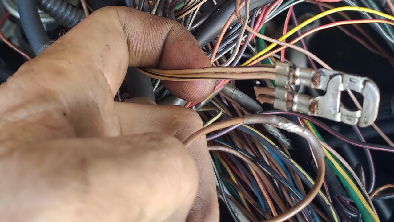
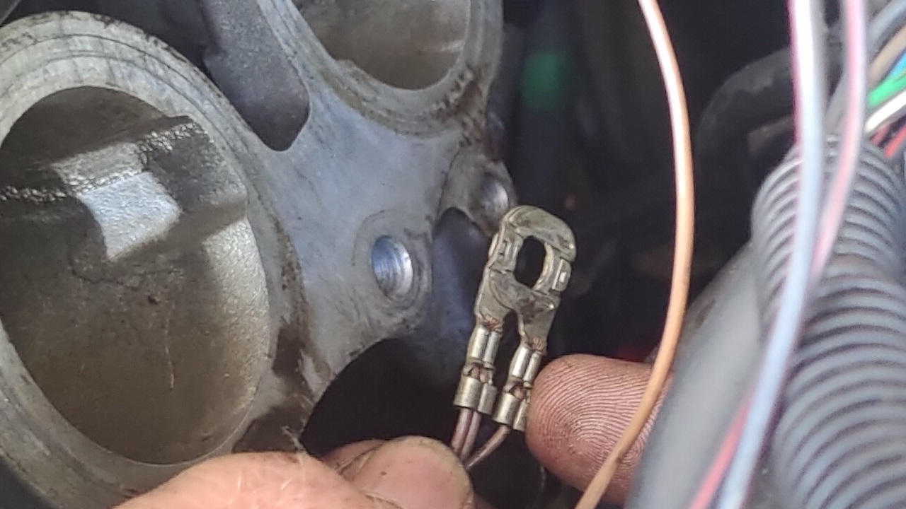
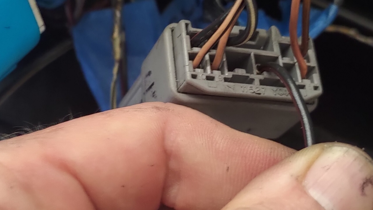
- Remove all BR (brown) grounds from manifold (pics 1 & 2). Connect them together if they're cut. Don't ground to engine!
- Find injector power on gray plug(pic 3), wire to Haltec injector relay pin87.
- Find ignition power also on gray plug, near INJ power(pic 4), wire to Haltech ignition relay pin87. Run a separate power wire from this power wire INTO Haltech pin A26.
- remove Toyota MAF, add 2 or 3 pin (I used a Haltech "GM Style" air intake temp. PN HT-010206). Add near TB inlet but away from heat.
- Optional: Disconnect OEM APPS and TB motor.
- Disconnect TPS pin 3. Leave disconnected.
- Replace R-Y wire (red w/ yellow stripe) on VVTi with B-R (black/red) (pics 5 & 6).
- Cam and Crank position sensors share a (-) signal, separate and wire each (-) individually.
- Connect all other sensors and output devices to the appropriate pins on the Elite 2500.
- Note: L-Y (Blue with Yellow stripe) on the IS300 is 5v supply from the ECU. This stays separate from all 12v power and will connect to the Elite 2500.
- Optional:Sever 5v (L-Y) power wire going to Vapor Pressure Sensor and reconnect to IS300 ECU
 |
 |
 |
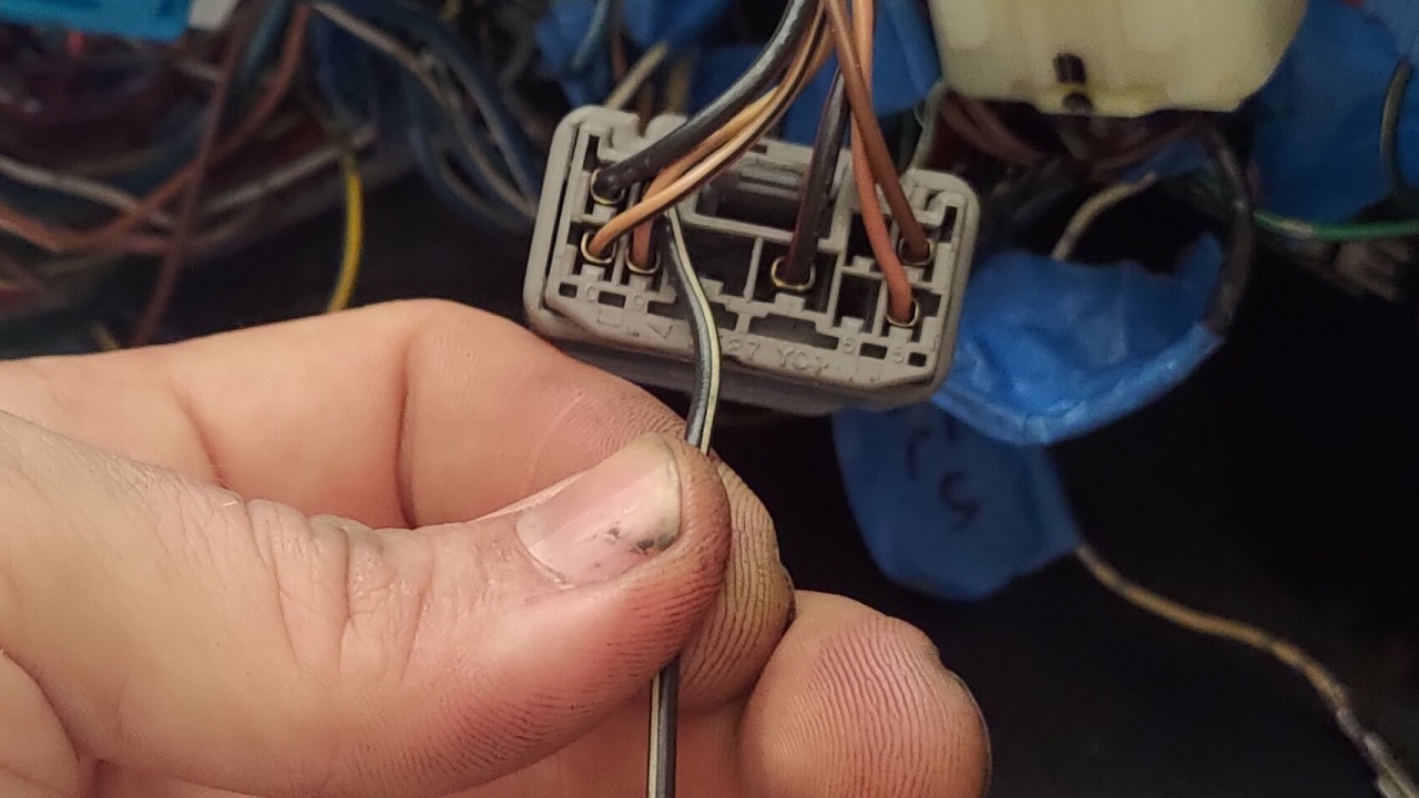 |
5 vvti before | 6 vvti after |
Normal Bosch relay wiring
|
Click here (or image) for larger view.
Jump to video on YouTube here.
|
|